Decoding the Float Switch: A Comprehensive Guide
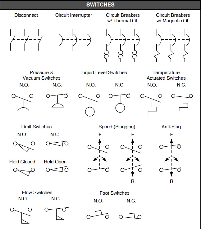
Ever wondered how your sump pump knows when to turn on or off? Or how your coffee machine prevents overflowing? The secret often lies within a small but mighty component: the float switch. Understanding the float switch schematic symbol is key to comprehending how these ingenious devices work in various applications, from managing water levels to controlling industrial processes.
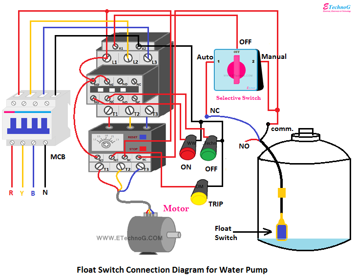
Float switches, in their essence, are level sensors that utilize buoyancy to detect the presence or absence of liquid. Their operation is beautifully simple yet remarkably effective. A float, often a sealed, hollow sphere, rises and falls with the liquid level. This movement activates a switch mechanism, triggering a specific action, such as turning a pump on or off. The float switch schematic symbol represents this functionality in electrical diagrams, allowing technicians and engineers to easily integrate them into system designs.
Visualizing a float switch diagram is like having a roadmap to its inner workings. These diagrams typically depict the switch in its various states – normally open (NO), normally closed (NC), or changeover (CO) – and illustrate how the float's position influences the switch contacts. Recognizing these symbols is crucial for accurate circuit interpretation and troubleshooting.
The history of float switch technology is intertwined with the rise of automation and industrial control systems. As industries sought more efficient and reliable ways to manage liquids, the need for automatic level sensing became apparent. Early float switches were relatively simple mechanical devices. Over time, advancements in materials, electronics, and manufacturing techniques led to the development of more sophisticated and robust float switch designs, including magnetically actuated switches and electronic level sensors.
The importance of float switch diagrams cannot be overstated. They serve as the universal language for understanding and implementing float switch circuits. Whether you're a homeowner troubleshooting a sump pump issue or an engineer designing a complex industrial system, understanding these symbols is paramount for safety, efficiency, and successful operation. Misinterpreting a float switch symbol could lead to malfunction, equipment damage, or even safety hazards.
A typical float switch diagram depicts the switch contacts and their relationship to the float's position. For instance, a normally open (NO) float switch symbol shows open contacts when the float is down, closing the circuit as the float rises. Conversely, a normally closed (NC) symbol shows closed contacts when the float is down, opening the circuit when the float rises. Changeover (CO) switches combine both functionalities, offering versatile control options.
Benefits of using float switches include automated liquid level control, preventing overflow or dry-run situations, and simplified system management. For example, in a sump pump application, a float switch automatically activates the pump when water levels rise, preventing basement flooding. In a water tank, it can shut off the inlet valve when the tank is full, conserving water and preventing spills.
Advantages and Disadvantages of Float Switches
| Advantages | Disadvantages |
|---|---|
| Simple and reliable operation | Limited accuracy in turbulent liquids |
| Cost-effective solution | Potential for clogging or fouling in dirty environments |
| Wide range of applications | Susceptibility to damage from corrosive liquids |
Best practices for implementing float switches include selecting the appropriate switch type based on the application, ensuring proper installation and wiring, and performing regular maintenance checks. For example, in a wastewater application, a robust, corrosion-resistant float switch is crucial. Regularly cleaning the float and checking for debris buildup can prevent malfunctions and ensure reliable operation.
Real-world examples of float switch applications include sump pumps, septic tanks, water tanks, industrial process control, and even coffee machines. In each case, the float switch provides a simple yet effective way to monitor liquid levels and automate system responses.
Challenges related to float switches can include clogging, fouling, corrosion, and mechanical wear. Solutions often involve selecting the right materials for the application, implementing filtration systems, and conducting regular maintenance.
FAQs about float switches often cover topics like switch types, wiring diagrams, troubleshooting tips, and application guidelines. Understanding these common questions and their answers can help users effectively implement and maintain float switch systems.
Tips and tricks for working with float switches include ensuring proper mounting and orientation, selecting the correct cable length and type, and understanding the specific requirements of the application. Careful attention to these details can ensure optimal performance and longevity.
In conclusion, understanding the float switch schematic symbol is fundamental to working with these versatile devices. From simple residential applications to complex industrial systems, float switches play a vital role in automating liquid level control and ensuring efficient operation. By grasping the principles of operation, understanding the various switch types, and following best practices for implementation and maintenance, you can effectively utilize float switches to enhance your systems and prevent costly or hazardous situations. Explore resources like manufacturer websites, online forums, and technical manuals to further your knowledge and enhance your understanding of float switch technology. Taking the time to learn about float switches empowers you to troubleshoot issues, design effective solutions, and maximize the benefits of this essential component. Embrace the power of the float switch and unlock a new level of control over your liquid management systems.
Understanding current transformer symbols
Unlocking the toyota rav4 hybrid price puzzle in the uae
Unlocking the power ford e450 engine size explained


