Decoding the Language of Circuits: Electrical Relay Symbols
Imagine stepping into a bustling control room, a network of wires and components humming with activity. Amidst this intricate tapestry, small symbols etched onto diagrams hold the key to understanding the flow of power and control. These symbols represent electrical relays, the unsung heroes of automation and power distribution systems. Understanding these graphic representations is essential for anyone working with electrical circuits, from seasoned engineers to aspiring technicians.
Electrical relay symbols are a standardized visual language used to represent various types of relays and their configurations within a circuit. These symbols provide a concise and efficient way to communicate complex information about the relay's function, contacts, and coil configuration. Think of them as shorthand for a detailed description of each relay's operation, allowing engineers to quickly grasp the overall circuit functionality.
The historical development of relay symbols mirrors the evolution of electrical engineering itself. As relays became more sophisticated, the need for clear and standardized representation became increasingly apparent. Early schematic diagrams often used ad-hoc symbols, leading to confusion and misinterpretations. The standardization of relay symbols brought clarity and consistency to circuit design, enabling engineers to collaborate more effectively.
The importance of understanding relay symbols cannot be overstated. These symbols are fundamental to reading and interpreting circuit diagrams, troubleshooting electrical systems, and designing new control systems. Misinterpreting a relay symbol can lead to costly errors, malfunctioning equipment, and even safety hazards. Proficiency in relay symbology is therefore a crucial skill for anyone working with electrical circuits.
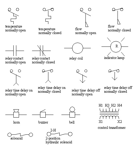
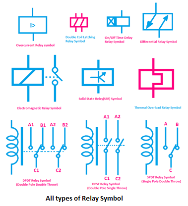
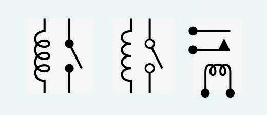
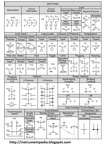
Relay symbols vary depending on the type of relay, its function, and the specific standard being used. For instance, a normally open contact (NO) is represented differently from a normally closed contact (NC). Similarly, different symbols are used to distinguish between latching relays, time-delay relays, and other specialized relay types. Understanding these nuances is crucial for accurate circuit analysis.
One significant benefit of using standardized relay symbols is improved communication. Engineers across the globe can readily understand a circuit diagram regardless of language barriers, thanks to the universally recognized symbols. This shared language facilitates collaboration and knowledge sharing within the electrical engineering community.
Another advantage is enhanced troubleshooting efficiency. When a circuit malfunctions, technicians can use the relay symbols on the diagram to quickly identify potential problem areas. This saves valuable time and resources in diagnosing and repairing electrical faults.
Furthermore, standardized relay symbols contribute to better circuit design practices. By using a common set of symbols, engineers can ensure clarity and consistency in their designs, reducing the risk of errors and improving overall system reliability.
Learning relay symbols is a gradual process. Start with the basic symbols for NO and NC contacts, then progress to more complex symbols representing different relay types and configurations. Practice reading and interpreting circuit diagrams, and use online resources and textbooks to reinforce your understanding.
Advantages and Disadvantages of Standardized Relay Symbols
| Advantages | Disadvantages |
|---|---|
| Improved Communication | Requires Learning and Familiarization |
| Enhanced Troubleshooting | Potential for Misinterpretation if not used correctly |
| Better Circuit Design | Variations between Standards |
Best Practices:
1. Adhere to recognized standards (e.g., IEC, ANSI).
2. Use clear and consistent labeling.
3. Ensure adequate spacing between symbols.
4. Cross-reference symbols with component specifications.
5. Regularly review and update symbol libraries.
Frequently Asked Questions:
1. What is a normally open contact? (Answer: A contact that is open in its de-energized state.)
2. What is a normally closed contact? (Answer: A contact that is closed in its de-energized state.)
3. What is a latching relay? (Answer: A relay that maintains its state even after the control signal is removed.)
4. What are the common standards for relay symbols? (Answer: IEC, ANSI, IEEE.)
5. Where can I find resources to learn more about relay symbols? (Answer: Textbooks, online tutorials, industry websites.)
6. How can I improve my understanding of relay symbols? (Answer: Practice reading and interpreting circuit diagrams.)
7. What are the benefits of using standardized relay symbols? (Answer: Improved communication, enhanced troubleshooting, better circuit design.)
8. What are the potential drawbacks of using relay symbols? (Answer: Requires initial learning, variations between standards.)
In conclusion, electrical relay symbols are the essential building blocks of circuit diagrams. Their standardized forms provide a clear and concise language for communicating complex information about relay function and circuit operation. Mastery of these symbols is vital for engineers, technicians, and anyone working with electrical systems. By understanding relay symbols, we can unlock the secrets of circuit diagrams, design efficient control systems, and troubleshoot electrical faults effectively. Take the time to learn and practice relay symbology – it's an investment that will pay dividends in your electrical engineering journey. As you delve deeper into the world of circuits, remember that these small symbols hold the key to understanding the larger picture of power and control. Embrace the language of circuits, and you'll be well-equipped to navigate the intricate world of electrical engineering.
Unlock your inner anime fighter exploring diverse combat styles
Lake gaston pizza littleton nc your lakeside pie guide
Unbeering the mystery where does beer come from


