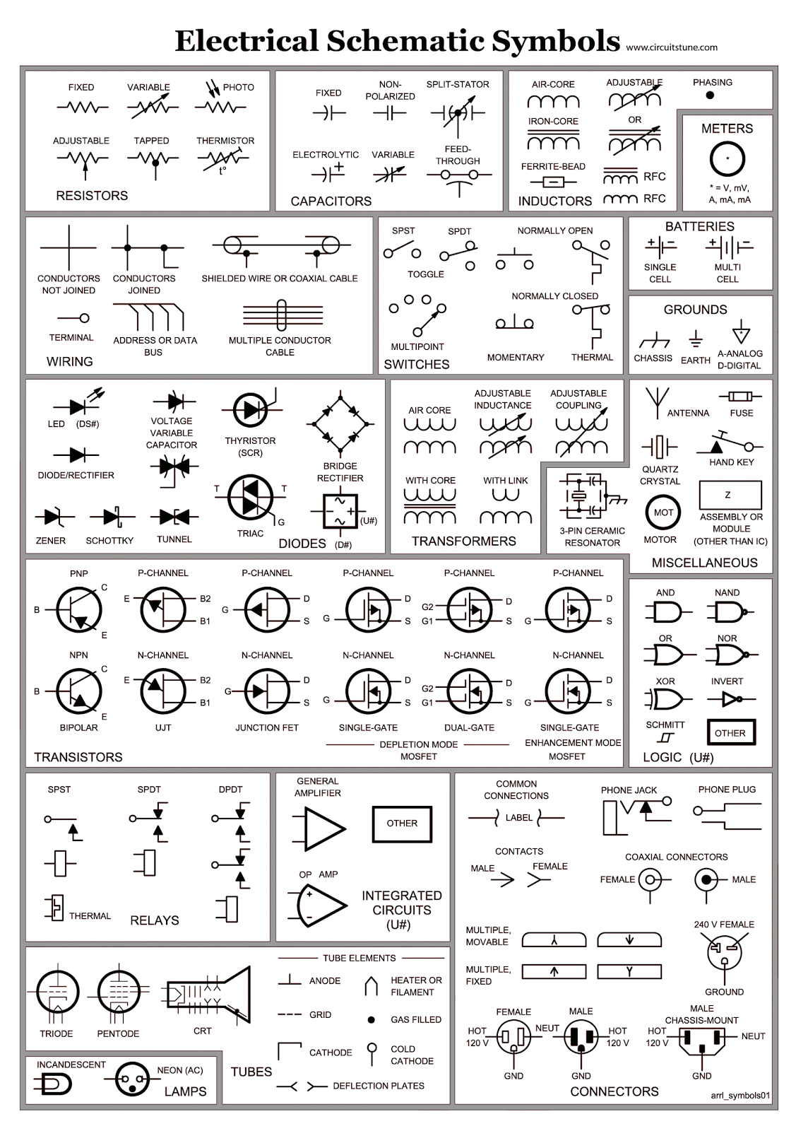
Decoding the Matrix Electrical Circuit Diagrams
Ever wonder how those intricate webs of lines and squiggles on circuit diagrams actually translate into working electronics? Those cryptic markings aren't random doodles; they're a universal language, a shorthand for electronic components that allows engineers and hobbyists alike to communicate complex ideas with clarity and precision. Welcome to the mesmerizing realm of electrical and electronic circuit symbols.
These graphic representations are more than just pretty pictures; they're the building blocks of every electronic device you can imagine. From the simple on/off switch in your flashlight to the complex microchips powering your smartphone, circuit symbols provide a visual map of how electricity flows and interacts with various components. Understanding these symbols is essential for anyone wanting to design, build, analyze, or repair electronic circuits.
The history of these symbols is intertwined with the development of electricity itself. As scientists and inventors began to unravel the mysteries of electrical currents, they needed a way to represent their discoveries and share their designs. Early depictions were often crude, resembling the physical components they represented. Over time, these representations evolved into standardized symbols, streamlining communication and fostering collaboration among engineers worldwide.
Imagine trying to explain a complex circuit using only words. It would be a tangled mess of descriptions, prone to misinterpretations and inaccuracies. Circuit symbols provide a concise and unambiguous representation, making it easy to understand the function and interconnection of components. This clarity is crucial for ensuring the proper operation and safety of electrical systems.
One of the main issues in the world of electrical diagrams is the potential for confusion if non-standard symbols are used or if the diagrams are poorly drawn. This can lead to errors in circuit construction, troubleshooting difficulties, and even safety hazards. Adhering to standardized symbols and maintaining clear, well-organized diagrams is paramount for effective communication and successful circuit implementation.
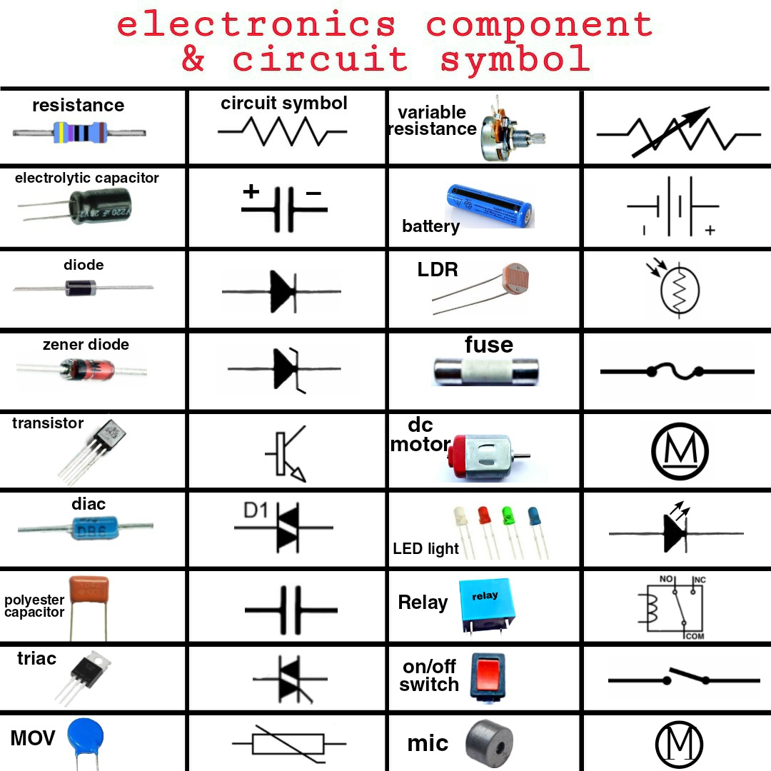
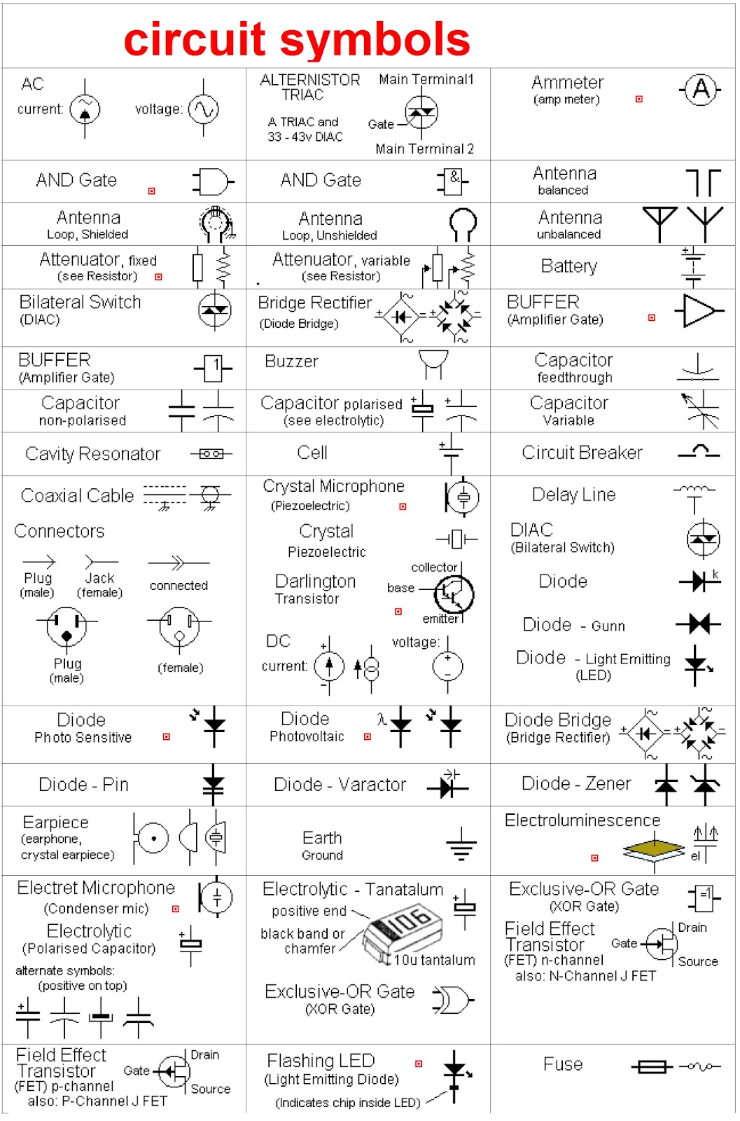
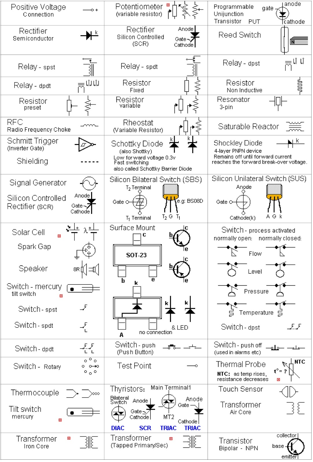
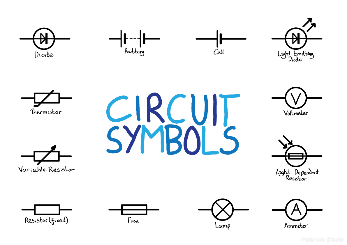
For instance, a resistor, which restricts the flow of current, is depicted as a zigzag line. A capacitor, which stores electrical charge, is represented by two parallel lines. These simple yet effective symbols instantly convey the function of each component within a circuit.
Benefits of using standardized electrical and electronic circuit symbols include: enhanced communication among engineers, simplified circuit design and analysis, and improved troubleshooting capabilities. For example, a technician troubleshooting a faulty circuit can quickly identify a blown fuse by recognizing its symbol on the diagram.
Creating a circuit diagram involves listing required components, sketching the layout, connecting components using appropriate symbols, and labeling each element. Successful circuit diagrams are clear, concise, and easy to understand.
Advantages and Disadvantages of Standardized Circuit Symbols
| Advantages | Disadvantages |
|---|---|
| Universal understanding | Requires initial learning |
| Simplified communication | Can be overwhelming for complex circuits |
| Efficient troubleshooting | Susceptible to misinterpretation if not standardized |
Best practices for using circuit symbols include: adhering to IEC or IEEE standards, maintaining consistent symbol size and orientation, using clear labels, ensuring adequate spacing between symbols, and regularly updating symbol libraries.
Frequently Asked Questions: What is a diode symbol? What does a ground symbol represent? How do I represent a transistor? What is the symbol for a battery? What does an inductor symbol look like? How do I represent a switch? What is the symbol for an AC source? What is the symbol for a DC source? These are just some of the common queries that demonstrate the importance of understanding these visual representations.
Tips and tricks for working with circuit symbols include utilizing software tools for creating and editing diagrams, referencing standard symbol libraries, and practicing drawing symbols by hand. This will improve your proficiency and ensure accuracy in your circuit designs.
In conclusion, electrical and electronic circuit symbols are the fundamental language of electronics. They provide a visual roadmap, allowing us to navigate the complexities of circuits and bring our electronic creations to life. From the simplest of circuits to the most intricate designs, these symbols are essential tools for communication, analysis, and implementation. Embracing the power of these symbols unlocks the potential for innovation and opens doors to a world of electronic possibilities. Understanding and utilizing standardized circuit symbols is crucial for anyone working with electronics, from seasoned engineers to budding hobbyists. Investing time in learning these symbols will pay dividends in your ability to design, build, and troubleshoot circuits effectively. Start exploring the world of circuit symbols today and unleash your electronic creativity.
Unlocking maritime mysteries decoding a boats story through its hull number
Unlocking efficiency the power of vacuum pumps in compressor systems
Exploring the subtle beauty of dusty rose paint
