Understanding Contactor Symbols in Electrical Diagrams
Imagine a world without standardized symbols in electrical diagrams. Chaos, right? Trying to decipher complex circuits would be like navigating a foreign city without a map. This is where the importance of standardized electrical symbols, such as the contactor symbol, becomes clear. They provide a universal language for electricians and engineers, simplifying complex designs and ensuring clear communication.
The electrical representation of a contactor is more than just a simple drawing. It’s a crucial element in understanding how electrical circuits operate. Contactors, essentially electrically controlled switches, manage power flow to larger loads, and their symbols on diagrams represent this function visually. These graphical representations allow us to trace power flow, understand control logic, and ultimately, troubleshoot and maintain electrical systems effectively.
The evolution of electrical symbols, including the contactor symbol, has mirrored the advancements in electrical technology itself. Early diagrams were often crude and varied, leading to confusion and misinterpretations. The need for standardization became evident as electrical systems became more complex. Organizations like the IEC (International Electrotechnical Commission) played a pivotal role in establishing globally recognized symbols, fostering clarity and safety in electrical design.
One of the core issues surrounding contactor symbols, or any electrical symbol for that matter, is the potential for variations or misinterpretations. While standardized symbols exist, slight differences can sometimes appear depending on the diagram's source or the software used to create it. This underscores the importance of referencing reputable standards and ensuring everyone involved in a project is on the same page regarding symbol interpretation.
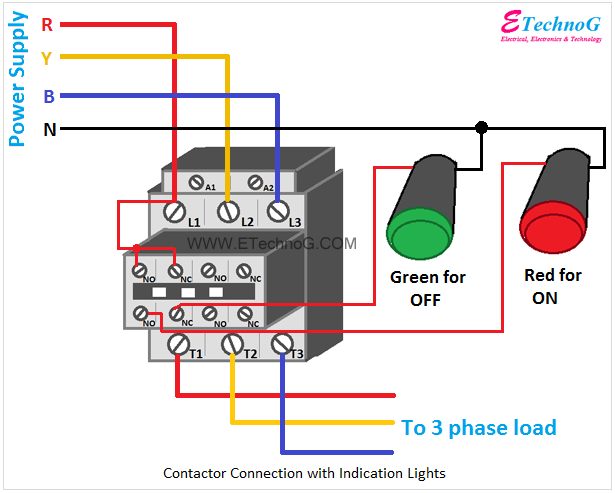
A contactor symbol typically consists of a coil and contacts. The coil represents the electromagnet that activates the contactor, and the contacts represent the switching mechanism that controls the power flow to the load. Auxiliary contacts, often represented by smaller lines connected to the main contacts, can also be included in the symbol to indicate additional control or signaling functions. Understanding these basic elements is crucial for deciphering the operation of a contactor within a larger circuit.
One benefit of using standardized contactor symbols is improved communication. These symbols provide a common language for engineers and technicians, reducing the risk of misinterpretations and errors. Another advantage is simplified troubleshooting. By quickly identifying the contactor symbol and its associated components in a diagram, technicians can more easily diagnose and resolve problems.
A practical example of the contactor symbol in action is in motor control circuits. The symbol clearly shows how the contactor switches the power on and off to the motor, based on the control signals it receives. Another example is in lighting control systems, where contactors can switch large banks of lights. The symbol helps visualize how the contactor manages the power distribution to these lights efficiently.
A common challenge related to contactor symbols is understanding the different types of contacts. Normally open (NO) and normally closed (NC) contacts perform opposite functions, and their symbols are slightly different. Properly identifying these contact types is essential for understanding the contactor’s operation. Solutions include referencing standard symbol guides or using software that automatically generates accurate symbols.
Advantages and Disadvantages of Standardized Contactor Symbols
| Advantages | Disadvantages |
|---|---|
| Clear Communication | Potential for variations in representation |
| Simplified Troubleshooting | Requires familiarity with standards |
| Efficient Circuit Design |
Best practice is to always consult the IEC or other relevant standards for accurate contactor symbol representation. Ensure consistency in symbol usage throughout a project. Clearly label all contacts and auxiliary components. Use software tools that adhere to established standards for symbol generation. Double-check diagrams for any discrepancies or ambiguities in symbol usage.
In conclusion, the electrical symbol for a contactor plays a vital role in clear communication and effective design within electrical systems. From simplifying complex circuit diagrams to enabling efficient troubleshooting, the standardized symbol empowers engineers and technicians alike. By understanding its nuances and adhering to best practices, we can harness the full potential of this powerful tool, ensuring the safe and reliable operation of electrical systems worldwide. Embracing this standardized language is essential for continued progress in the field of electrical engineering and ensures that everyone speaks the same language, from the design phase to maintenance and troubleshooting.
Decoding hewitt boat lift costs your ultimate guide
Unlocking the vibrancy the blue green and orange color palette
Crafting a paper boat hat a fun and creative adventure


